|
Brand Name: INSBUD
Model Number: SDF-W
Place of Origin: Jiangsu, China (Mainland)
Automatic water level controller
Application
The product is designed in integrated circuit, combined with the upgrade
of water level classification through upper and lower pools of water tower
of high-rise buildings. It can effectively prevent pool drainage, water overflow by automatically water supplement or decrease, absolutely prevent the pump from damaged. It is very suitable for the water supply project on water towers or wells in
schools, industrial and mining enterprises from urban or rural. More, it is
widely used in printing, chemical, food, beverage, wine, sugar and so on.
Probe Installations
(I) Single-control UP pool (water storage) installation instructions shown (I) .
A(red)—Upper water level control point. When water level gets to A point,
the probe touch water and controller can stop the pump by auto.
B(blue)—Lower water level control point. When water level gets off B point,
the probe out of reach water and controller can start the pump by auto.
C(black)—Should be placed in bottom of pool as the common line.
D(green) and E(yellow)are connected with C (black).
(II) Single-control DOWN pool(drain water)installation instructions shown (II)
E—Upper water level control point. When water level gets to E point,
the probe touch water and controller can start the pump by auto.
D—Lower water level control point. As liquid level gets off D point,
the probe out of reach water and controller can stop the pump by auto.
C—Should be placed in bottom of pool as the common line.
A&B—disconnected
(III) Lack of water protection installation instructions shown (III)
C&D—Lower water level control points. When water level gets off this point,
C or D probe out of reach water and controller can stop the pump by auto.
E&C—short-connected;
A&B—disconnected
(IV) Joint control UP and DOWN pool installation instructions shown (IV)
A—Upper water level control point in UP pool. When water level gets to A point,
the probe touch water and controller can stop the pump by auto.
B—Lower water level control point in UP pool. When water level gets off
A point, the probe out of reach water and controller can start the pump by auto.
C—Should be placed in bottom of UP and DOWN pools as the common line.
D—Lower water level control point in DOWN pool. When water level gets off D point,
the probe out of reach and controller can stop the pump by auto.
E—Upper water level control point in DOWN pool. When water level gets to E point,
the probe reach water and controller can start the pump by auto. Then pool starts to drain water. If not, E point disconnected
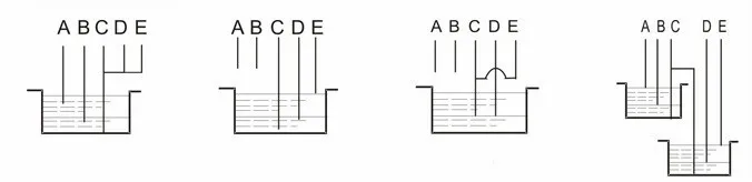
(I) (II) (III) (IV)
Technical Specifications
working Voltage Range: AC220V/50HZ
Voltage scope: 85%~110%
Capacitance: 5A
Consumed capacitance:AC220V/5A
Temperature: -10°C~+50°C
Relative Humidity: <95%
Dimension: 71.2×80×62(mm)
Weight: 165g


- Product Listing Policy - Intellectual Property Policy and Infringement Claims
- Related Links
- Privacy Policy
- Terms of Use
ICP License: 浙ICP备2023052164号 © Coowor.com. All rights reserved.
Tel: +86 10 65447649 E-mail: coowor@coowor.com
Copyright © Hangzhou Coowor Network Technology Co., Ltd. All Rights Reserved.